Lesson 6 Overview
LESSON 6: SURFACE ANALYSIS
Lesson 6 Overview
Introduction
Once you have field data, whether as a result of interpolation, or
based on more complete original data, perhaps from aerial surveys or
remote-sensed imagery, you will likely want to analyze it in a variety
of ways. In this lesson, we look at the fundamentals of such analysis
and in the project explore the application of such methods to field
data.
Learning Objectives
By the end of this lesson, you should be able to
- describe data models for field data: regular grid, triangulated
irregular network, closed form mathematical function, control points;
and discuss how the choice of model may affect subsequent analysis
- explain the map algebra concept and describe focal operations, local
operations and between-map operations
- understand the idea of slope and aspect as a vector field
- explain how slope or gradient can be determined from a grid of
height values
- describe how surface aspect may be derived from a grid of height
values
- re-express these operations as local operations in map algebra
- describe how map algebra operations can be combined to develop
complex functionality
Reading Assignment
You need to read the following selections from the textbook:
- Section 8.2, "Modeling and storing field data," pages 213-20
- Section 8.4, "Derived measures on surfaces," pages 234-42
 The course text does not cover all the material we need, so there is
some information in the commentaries for this lesson that is not
covered at all in the textbook reading assignments. In particular, read
carefully the online information for this lesson on "Map Algebra" and
"Vector Fields."
The course text does not cover all the material we need, so there is
some information in the commentaries for this lesson that is not
covered at all in the textbook reading assignments. In particular, read
carefully the online information for this lesson on "Map Algebra" and
"Vector Fields."
After you've completed the reading, get back online and supplement
your reading from the commentary material, then test your knowledge
with the self-test quiz.
Lesson 6 Deliverables
This lesson is one week in length. The following items must be
completed by the end of the week. See the Calendar tab, above,
for the specific date.
- Complete the self-test quiz satisfactorily (you have an unlimited
number of attempts and must score 90% or more).
- Complete Project 6, where you will apply surface
analysis methods, including more complex map algebra operations, to the
problem of choosing a suitable location for a new high school. (The
materials for Project 6 can be found under the Lessons tab, in the
Lesson 6 folder.)
- Continue the Quarter-long Project revising your
proposal in light of comments received, and submitting it. See the
Week 6 directions for details. (This link opens in a new window.)
Questions?
If you have any questions now or at any point during this lesson,
please feel free to post them to the Lesson 6 thread of the
Lesson Content Discussion Forum. (That Discussion Forum can be
accessed at any time by clicking on the Communicate tab,
above, and then scrolling down to the Discussion Forums
section.)
Ready to continue? Click on the "Next" link, above, to continue with
this lesson.
LESSON 6: SURFACE ANALYSIS
Commentary - Chapter 8, Section 8.2, "Modeling and Storing Field
Data"
Continuous phenomena and field data
It is always important in the context of geospatial data to
distinguish between the phenomenon itself and its representation in
data. This is especially so with data that represent phenomena
theoretically measurable at all locations but in practice only measured
at sample locations. The phenomenon (say atmospheric pressure) could,
in principle, be measured at every location on Earth, but in practice
it cannot be. Instead, we work with a set of measurements at
control points and interpolate these to generate a
field that approximates the continuous phenomenon. How the control
points and any subsequent interpolation results are stored can have
important effects on subsequent analysis steps.
On pages 214-20 a variety of methods for storing field data are
discussed, and some of their advantages and disadvantages considered.
The schemes you are most likely to encounter in practice are point
sampling schemes of one kind or another, particularly grid-based
samples. Grid-based sampling schemes are particularly useful as the
basis for surface analysis operations, because the equally-spaced
measurements simplify many mathematical operations. Further, since any
other surface data can be readily converted to this format by
interpolation, in the remainder of this lesson we assume that field
data are available as a grid.
However, it is important to bear in mind that grids of field values
often did not start out that way, but were produced by interpolation
from a much sparser set of control points. As a consequence of this,
you should check any associated metadata before assuming the accuracy
of data values in a grid.
Ready to continue? Click on the "Next" link, above, to continue with
this lesson.
LESSON 6: SURFACE ANALYSIS
Commentary - Map Algebra
"Map Algebra" is material not covered in the
course text.
Map algebra is a framework for thinking about analytical operations
applied to
field data. It is most readily understood in the case of field data
that are stored as a grid of values, but is in principle applicable to
any type of field data.
The map algebra framework was devised by Dana Tomlin and is presented
in his 1990 book Geographical Information Systems and Cartographic
Modeling (Prentice Hall: Englewood Cliffs NJ), which you should
consult for a more detailed treatment than is given here. Another good
reference on map algebra (and much else besides) is GIS Modeling in
Raster (Wiley: New York, 2001) by Michael DeMers.
Many GISs (including ESRI ArcGIS) support map
algebra. In ArcMap, the tool most closely related to map algebra is
called the 'map calculator'.
Basic concepts
The fundamental concepts in map algebra are exactly as in
mathematical algebra, that is
- Values are the 'things' on which the algebra operates.
Input data and output data (results) are presented as grids of values.
Note, that as has already been discussed, values can be categorical (
nominal or
ordinal) or numerical.
- Operators may be applied to values to transform them, or
between two or more values to produce a new value. In mathematical
algebra the minus sign '�' is an operator that negates a single value
when placed in front of it, as in �5. The plus sign '+' is also an
operator, signifying the addition operation, which, when applied
between two values, produces a new value: 1 + 2 = 3
- Functions are more complex, but still well defined
operations, that produce a new value from a set of input values. The
input set may be a single value, as in log10({100}) = 2, or
a set of values, as in average({1, 2, 3, 4}) = 2.5.
Now consider two small grids of values:
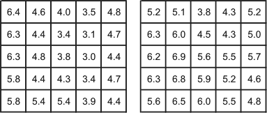
Two small grids of values representing typical data
fields
If we want to apply an operation or function to these values, how
should we proceed? It is apparent that we have a number of options, and
map algebra clearly defines these as described in the following
sections. Note that we refer to these grids as [left_grid] and
[right_grid] when necessary in the discussion.
Local operations and functions
A
local operation or function in map algebra is simply
applied to each individual cell value in isolation. For example, the
local negation operation signified by the minus sign '�' and applied to
the left hand grid above grid results in the following output grid,
�[left_grid]:

Result of the local negation
operation applied to [left_grid] from the previous figure
Applying a local operation between two grids involves
applying the operation to values in corresponding positions in each
grid, and recording the result in the corresponding position in the
output grid. For example the result of the + operation applied between
the two grids above is, [left_grid] + [right_grid]:

Result of the local addition
operation applied between [left_grid] and [right_grid]
Another example is a local maximum operation between two (or more)
grids, which assigns to each output location the maximum of the values
at the corresponding location in the input grids. The result of
local_max( [left_grid] , [right_grid] ) applied to the two example
grids above is:

Result of the local_max operation
applied to [left_grid] and [right_grid]
Focal operations and functions
We can also apply an operator, or, more often, a function,
focally to a grid. This means that the value at each
location in the output grid is arrived at by combining values
focused at the corresponding location in the input grid or grids.
A simple example is focal_max which would assign to each
output location the maximum of the values in the that location and its
immediate neighbors in the input grid. The result of applying a focal
maximum function to left_grid is:
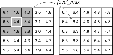
Result of the focal_max(
[left_grid] ) function. The result at each location in the
output grid is determined from the set of values at that location and
neighboring locations in the input grid, as shown by the shading.
Many functions can be applied focally in this way, such as maximum,
minimum, mean (or average), median, standard deviation, and so on. In
addition to the function itself, the output grid will depend on how the
focal neighborhood is defined in a particular case. In the
above example, the focal neighborhood is the grid cell itself and the
eight immediate neighbors. Some alternative neighborhood definitions
are shown below:

Some alternative definitions of the focal
neighborhood relative to the central cell of this small grid.
A different choice of focal neighborhood will alter the output grid
that results when a focal function is applied. Notice that there is no
requirement that the neighborhood be symmetrical about the focal grid
cell, as shown in the last example. A non-symmetrical neighborhood like
this might have application in understanding how air pollution spreads
given a prevailing wind direction.
Zonal operations and functions
Zonal operations and functions are an extension of the
focal concept. Rather than define operations with respect to each grid
cell, a set of map zones are defined (for example, counties) and
operations or functions are applied with respect to these zones. You
have already seen an example of a zonal function in practice in the
Texas redistricting project in lesson 1, where estimated numbers of
voters for each party were summed for Congressional Districts.
Global operations and functions
Finally, some operations and functions are
global, meaning that the values at each grid cell in an
output grid may potentially depend on the values at all grid
cell locations in the input grid(s). An operation that finds the cost
(in time or money) of the shortest path from a specified location (say
a school) to every other location may have to take into account values
at all locations in a grid to find the correct answer (travel cost
might be based on the land cover type and its slope).
Ready to continue? Click on the "Next" link, above, to continue with
this lesson.
LESSON 6: SURFACE ANALYSIS
Commentary - Vector Fields
"Vector Fields" is covered in the text, but in a number of
different places.
So far in this course, we have only considered
attribute data types that are single-valued whether that value is
categorical or numerical. In spatial analysis, we frequently encounter
attributes that are not conveniently represented in this way. In
particular, we may need to use vectors to represent some types
of data.
A vector is a quantity that has both value (or magnitude)
and direction. The most obvious vector in real life application is
wind, which has a speed (its magnitude or strength), and direction.
Without wind direction information, wind speed information is not very
useful in many applications. For example, an aircraft navigator needs
to know both wind speed and direction to accurately plot a course, and
to estimate arrival times, or fuel requirements.
As mentioned in the text (pages 236-7), the most fundamental
vector field is the
gradient
field associated with any
scalar (i.e., simple numerical) field. This often has practical
applications. For example, the gradient field of atmospheric pressure
is important in meteorology in determining the path of storm systems
and wind directions.
Ready to continue? Click on the "Next" link, above, to continue with
this lesson.
LESSON 6: SURFACE ANALYSIS
Commentary - Chapter 8, Section 8.4, "Derived Measures on Surfaces"
The measures discussed in this section are just a small sample of the
types of surface analysis measure that can be devised. In this
commentary, we focus on how these can be expressed as
map algebra operations.
Relative relief
Relative relief, from the definition on page 235 in the text, is
readily expressed as a map algebra function:
rel_relief = focal_max( [elevation] ) � focal_min(
[elevation] )
where the
focal region is defined accordingly.
Surface gradient and aspect
Surface
gradient is more complex, requiring a number of steps. First, two
focal functions to calculate the slope in two orthogonal directions
must be defined. These will be similar functions, but must have
specially defined focal areas that pick out the immediately adjacent
grid cells on either side of the focal cell in each of the two cardinal
directions.
If these slopes are called ew-gradient (for east-west) and
ns-gradient (for north-south), then the overall gradient is given
by
gradient = square-root( ( arctan(
ew-gradient ) )2 + ( arctan( ns-gradient
) )2 )
and the overall aspect is given by
aspect = arctan( ( ew-gradient ) / (
ns-gradient ) )
These examples should give you a feel for the flexibility of the map
algebra framework. In this week's project you will have an opportunity
to explore map algebra more thoroughly in a more practical setting.

Ready? Take the Surface Analysis quiz (Sections 8.2 and 8.4, plus
commentaries) to check your knowledge! Click on the "Next" link, above,
to access the self-test quiz on Surface Analysis. You have an unlimited
number of attempts and must score 90% or more.
Ready to continue? Click on the "Next" link, above, to begin the
Surface Analysis Quiz.
LESSON 6: SURFACE ANALYSIS
Final Activities for Lesson 6
Now that you've completed the readings and the self-test quiz for
this lesson, it is time to apply what you've learned!
The following links will open in a new browser window.
- Complete Project 6, where you will apply surface
analysis methods, including more complex map algebra operations, to the
problem of choosing a suitable location for a new high school. (When
you are done reviewing this Web page, click on the "Next" link, above,
to begin Project 6. The materials for Project 6 can also be found under
the Lessons tab, in the Lesson 6 folder.)
- Continue the Quarter-long Project revising your
proposal in light of comments received, and submitting it. See the
Week 6 directions for details. (This link opens in a new window -
the materials for the Quarter-long Project can be also be found under
the Lessons tab.)
Ready to continue? Click on the "Next" link, above, to begin Project
6.
PROJECT 6: RASTER MAP ANALYSIS
Overview
Background
Now let's continue our work on data from Central Pennsylvania, where
Penn State's University Park campus is located. This week we'll see how
this ancient topography affects the contemporary problem of determining
potential locations for a new high school.
Introduction
The Centre region of Pennsylvania is the fastest growing region in
the state, largely as a result of the presence of Penn State in the
largest town of State College. Growth is putting pressure on many of
the region's resources, and some thought is currently being given to
the provision of high schools in the region. In this project we will
use raster analysis based on road transport in the region to determine
potential sites for a new school. This will demonstrate how complex
analysis tasks can be performed by combining results from a series of
relatively simple analysis steps.
Project Resources
The data files you need for Project 6 are available here in a zip
archive file. If you have any difficulty downloading this file, please
contact me.
That file is 1.65 Mb and will take approximately 4 minutes to
download over a 56 Kbps modem. Once you have downloaded the file,
double-click on the project6materials.zip file to
launch WinZip, PKZip, 7-Zip, or another file compression utility.
Follow your software's prompts to decompress the file. Unzipping this
archive you should get an ArcMap project file (centreSchools.mxd
), a geodatabase file (centreSchools.mdb) and a folder
containing topographic data layers (topo). Open the ArcMap
file to find layers as follows:
Layers in the ArcMap file (centreSchools.mxd) are as
follows:
- highSchools - four high schools in Centre County,
Pennsylvania
- centreCountySchoolDistricts - the corresponding school
districts
- majorRoads - major roads in the region
- localRoads - minor roads in the region
- centreCountyCivilDivisions - showing townships and boroughs
in the county
- representativePopInSchoolDistricts - a point layer derived
from census block group centroids with attributes for total population
and children aged between 5 and 17
- centreBGdemographics - more complete demographic data from
the 2000 census associated with polygons representing the block groups
for which the data were collected
- centretopo100 - the topography of the county at 100 meter
resolution.
Summary of Project 6 Deliverables
For Project 6, the items you are required to have in your write-up
are:
 Describe in your write-up how the distance analysis
operation works, including commentary on how you would combine multiple
distance analyses results (one for each high school) to produce an
allocation analysis output and the differences in the straight line
distance allocation and the actual allocation of places
to school districts in the present example.
Describe in your write-up how the distance analysis
operation works, including commentary on how you would combine multiple
distance analyses results (one for each high school) to produce an
allocation analysis output and the differences in the straight line
distance allocation and the actual allocation of places
to school districts in the present example.- Describe in your write-up how you created the roads raster.
- Perform the cost weighted distance analysis for high
schools using the roads raster layer. Examine the resulting allocation
layer. How does it differ from the straight-line distance allocation
result? Do the roads account for all the inconsistencies between the
straight line distance allocation and the actual school districts?
Answer these questions in your write-up.
- Estimate the number of the school age children in the four
school districts, and also in the road travel cost weighted distance
allocation zones associated with each school, and put these estimates
in your write-up. Also describe how you arrived at your estimates.
- Insert into your write-up a map and other details of your
proposals for a new high school and associated district, including
arguments for and against, possible problems with your analysis, maps,
and explanations of any analysis carried out.
Questions?
If you have any questions now or at any point during this project,
please feel free to post them to the Project 6 thread on the
Project Discussion Forum. (That Discussion Forum can be accessed at
any time by clicking on the Communicate tab, above, and then
scrolling down to the Discussion Forums section.)
Ready to continue? Click on the "Next" link, above, to continue with
this project.
PROJECT 6: RASTER MAP ANALYSIS
Allocation Based on Straight Line Distance
As in last week's project, you should ensure that the Spatial
Analyst - Options... are set appropriately before doing any
analysis. In particular use the centreCountyCivilDivisions
layer as an Analysis mask and for the Extent. Also
set the Temporary working directory to something sensible and
choose to save the analysis results in the
same coordinate system as the data frame (the second option).
The first analysis we will do uses a built-in function of the Spatial
Analyst to allocate each part of the map to the closest one of a set of
points. This is the raster equivalent of proximity polygons.
- Select the Spatial Analyst - Distance... - Straight Line
Distance... menu option.

The Straight Line dialog with parameters set to
generate an allocation of areas to high schools.
Running straight line distance analysis will produce two layers, a
distance layer, and an allocation layer. The distance layer will look
something like this:

Results of the straight line distance analysis for
high schools
While the allocation layer should look like this:
Results of the straight line distance allocation
- You can further analyze these layers. For example, it may be easier
to read the distance analysis if you create contour lines. The results
of the allocation analysis can be converted to vector polygons, which
may make subsequent analysis operations easier to perform.
Describe of how the distance analysis operation works in
your Project 6 write-up. In your description, comment on how you would
combine multiple distance analyses results (one for each high school)
to produce an allocation analysis output. Finally, comment on the
differences in the straight line distance allocation and the
actual allocation of places to school districts. (You will need to
look at the roads, topography, and minor civil divisions to make sense
of this.)
Ready to continue? Click on the "Next" link, above, to continue with
this project.
PROJECT 6: RASTER MAP ANALYSIS
Distance Analysis Over Roads (1)
Clearly roads are a major factor in the difference between straight
line distance allocation of school districts, and actual school
districts. In this part of the project you will create a raster layer
representing the roads of Centre County to use in a second roads-based
distance analysis.
Creating a roads raster layer using map algebra operations
- Using the Spatial Analyst - Convert - Features to Raster...
tool make raster layers from the majorRoads and localRoads
layers.
- Use the Spatial Analyst - Reclassify... and Spatial
Analyst - Raster Calculator... tools, to manipulate and combine
these layers into a single roads layer where major road cells have
value 1, minor road cells have value 2, and off-road cells have some
high value (say 100).
This is a multistep operation�you will have to create intermediate
Calculation layers and combine those in various ways to arrive at
something like this:.

Part of a roads raster layer. Red cells have value 1,
orange cells have value 2, and clear (that is, background color) cells
have value 100.
Describe how you created the roads raster in your Project 6
write-up.
Ready to continue? Click on the "Next" link, above, to continue with
this project.
PROJECT 6: RASTER MAP ANALYSIS
Distance Analysis Over Roads (2)
Using the roads raster layer for distance analysis
Distance analysis using a roads raster layer is straightforward. The
values in the layer are regarded as 'weights' indicating how much more
expensive it is to traverse that cell than if the cell were unweighted.
Thus, with the roads layer just created, traveling on major roads
incurs no penalty, travelling on local roads is twice as expensive
(takes twice as long), and traveling off-road is very slow indeed (100
times slower). These are not accurately determined weights, but serve
to demonstrate the potential of these methods.
- Select the Spatial Analyst - Distance... - Cost weighted...
option to bring up the Cost Weighted dialog:

The dialog used to specify parameters for distance
analysis to high schools over the road network
- Now, you should repeat the previous distance analysis, but weighted
by the roads raster layer you created. Also, request an Allocation
output from the analysis. (If you are interested in later experimenting
with the Distance.. Shortest path... tool you should also request a
Direction output, but this is not required for the
project.)
Perform the cost weighted distance analysis for high
schools using the roads raster layer. Examine the resulting allocation
layer. How does it differ from the straight-line distance allocation
result? Do the roads account for all the inconsistencies between the
straight line distance allocation and the actual school districts?
Respond to these questions in your Project 6 write-up.
Ready to continue? Click on the "Next" link, above, to continue with
this project.
PROJECT 6: RASTER MAP ANALYSIS
Allocation Based on Road Distances
Estimating school age population in each school district
- Using the Spatial Analyst - Zonal Statistics tool you can
estimate the number of age 5 to 17 children in each school district:

Specify here the dataset containing the zones for
which you want to compile summary statistics for a raster dataset.
- To prepare for this you will need to create a raster layer
representing the school age population for the region. There are a
number of options available, starting with either the
representativePopInSchoolDistricts point data, or the
centreBGdemographics polygon layer. Whatever way you do it, use the
AGE_5_17 variable as an approximation for the count of school
age children.
Estimate the number of the school age children in the four
school districts, and also in the road travel cost weighted distance
allocation zones associated with each school, in your Project 6
write-up. Include a description of how you arrived at your estimates.
Ready to continue? Click on the "Next" link, above, to continue with
this project.
PROJECT 6: RASTER MAP ANALYSIS
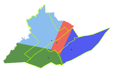
And so... where to put a new school, and what should be its
district?!
The headline above summarizes the last part of the project. Based on
the analyses already carried out, and any other analyses required to
support your answer, locate a new high school in Centre County!
As a minimum you should use the ArcMap editing tools to add a school
to the highSchools layer and create a map of the new school,
and what the new school's associated district would be. You should
insert this map together with a description of how you arrived at it
into your Project 6 write-up. Note that school districts are always
made up of a contiguous collection of townships and/or boroughs, and
that the centreCountyCivilDivisions layer shows these.
Insert into your Project 6 write-up a map and other details
of your proposals for a new high school and associated district,
including arguments for and against, possible problems with your
analysis, maps, and explanations of any analysis carried out.
Ready to continue? Click on the "Next" link, above, to continue with
this project.
End of Project 6 - Remember, if you have any
questions, post them to the appropriate Discussion Forum.
QUARTER-LONG PROJECT
Week 6: Revising Your Project Proposal
Based on the comments you received from other students and from me,
revise your original project proposal and submit a final version this
week. Timely submission of your revised project is worth up to 6 of the
30 total points available for the quarter-long project. Note that you
may lose points if your proposal suggests that you haven't been
developing your thinking about your project.
In your revised proposal you should try to respond to as many of the
comments made by your reviewers as possible. However, it is OK to stick
to your guns! You don't have to adjust every aspect of the proposal to
accommodate reveiwer concerns, but you should consider every point
seriously, not just ignore them.
Your final proposal should be between 600 and 800 words in length and
should include the same items as before:
- Topic and scope
- Aims
- Data
- Data sources
- Intended analysis and outputs -- This is a little different from
before. It should list some specific outputs (ideally several specific
items) that can be used to judge how well you have done in attaining
your stated aims. Note that failing to produce one of the stated
outputs will not result in an automatic loss of points, but you will be
expected to comment on why you were unable to achieve everything you
set out to do (even if that means simply admitting that some other
aspect took longer than anticipated, so you didn't get to it).
Post your revised (final) project proposal to your web site,
as part of the "Quarter-long Project" section of your site. Use the
course email system to notify the instructor that you have done this
including a URL.
Questions?
If you have any questions now or at any point during this project,
please feel free to post them to the Quarter-long Project
Discussion Forum. (That Discussion Forum can be accessed at any
time by clicking on the In Touch tab, above, and then
scrolling down to the Discussion Forums section.)
That's it for the quarter-long project this week!